Raspberry Pi
Contingut
- 1 Introducció
- 2 Imatge Raspbian wheezy
- 3 Primer exemple GPIO (General Purpose Input/Output)
- 4 RaspiCAM (mòdul de càmera)
- 5 PiTFT
- 6 Configuració wifi USB
- 7 Muntar una memòria USB Flash (pen drive)
- 8 Fer una ISO d'una targeta SD
- 9 USB Audio Card
- 10 LED chaser: I2C i MCP23017 a la RPi
- 11 Fer conectors per la GPIO. Conectors per crimpar i ficar en els housings
- 12 Setting up a Raspberry Pi as an access point in a standalone network (NAT)
- 13 Streaming amb RPi3 + Raspicam
Introducció

- http://reviews.cnet.com/desktops/raspberry-pi-model-b/4505-3118_7-35332544.html
- http://tecnologia.elpais.com/tecnologia/2012/12/07/actualidad/1354901348_817529.html
The Pi has those capabilities and others in part because of its surprisingly powerful embedded silicon. The core CPU/GPU/system memory comes from a single Broadcom BCM2835 system-on-a-chip (SoC). The SoC includes a 700MHz ARM processing core that gives the Pi the same processing power as an iPhone 3G. A separate, dual-core video processor supports 1080p HD video encoding and decoding. And 256MB of DDR2 system memory rounds out the package.
Along with the SoC, the Pi has an assortment of hardware ports. This Model B version includes a 10/100 Ethernet port as well as a pair of USB 2.0 jacks. For video output you get a full-size HDMI port, as well as a composite video output. Aside from HDMI audio output, you also get a single 3.5mm analog output.
Imatge Raspbian wheezy
downloads:
La imatge bàsica i típica és la Raspbian wheezy
If you’re just starting out, this is the image we recommend you use. It’s a reference root filesystem from Alex and Dom, based on the Raspbian optimised version of Debian, and containing LXDE, Midori, development tools and example source code for multimedia functions.
Direct download 	2012-12-16-wheezy-raspbian.zip
SHA-1 	514974a5fcbbbea02151d79a715741c2159d4b0a
Default login 	Username: pi Password: raspberry
comprovem que s'ha descarregat bé:
$ shasum 2012-12-16-wheezy-raspbian.zip
514974a5fcbbbea02151d79a715741c2159d4b0a  2012-12-16-wheezy-raspbian.zip
To use an image file, you will need to unzip it and write it to a suitable SD card using the UNIX tool dd.
Instruccions per gravar la imatge a la targeta SD:
$ df -h
S. fitxers            Mida En ús Lliure %Ús Muntat a
...
/dev/mmcblk0p1        3,7G  128K  3,7G   1% /media/69C5-1327

$ sudo umount /dev/mmcblk0p1

$ sudo dd bs=4M if=~/raspberrypi/2012-12-16-wheezy-raspbian.img of=/dev/mmcblk0p1
462+1 registres llegits
462+1 registres escrits
1939865600 octets (1,9 GB) copiats, 565,168 s, 3,4 MB/s

$ sudo sync
Doncs no ha funcionat, al final ho he fet amb la interfície gràfica, imagewriter:
$ sudo apt-get install usb-imagewriter
$ sudo imagewriter
important!: millor executar imagewriter des d'Aplicacions > Accessoris que no pas de línia de comandes.
Buscar la IP de la Raspberry
Si la tinc connectat a la tele només cal mirar la pantalla. Però si no és el cas, que és lo normal, i no sé quina IP m'ha agafat, només cal fer des del portàtil:
$ nmap -sP 192.168.1.1-255
i fa un descobriments de totes les IP que hi ha a la xarxa.
update Jordi Binefa (oct 2018):
$ sudo nmap -sP 192.168.1.0/24 | awk '/^Nmap/{ip=$NF}/B8:27:EB/{print ip}'
Fixing the 100% rootfs usage
A mi em passa el mateix que aquí:
$ df -h
Filesystem      Size  Used Avail Use% Mounted on
rootfs          1.8G  1.7G     0 100% /
/dev/root       1.8G  1.7G     0 100% /
devtmpfs         93M     0   93M   0% /dev
tmpfs            19M  224K   19M   2% /run
tmpfs           5.0M     0  5.0M   0% /run/lock
tmpfs            37M   68K   37M   1% /run/shm
/dev/mmcblk0p1   56M   17M   40M  30% /boot
tmpfs            37M  720K   37M   2% /tmp
tinc el rootfs totalment ple i no m'estranya que pugui anar lent.
$ sudo raspi-config
i utilitzo l'opció expand_rootf. Reinicio i ara ja ho he expandit:
$ df -h
Filesystem      Size  Used Avail Use% Mounted on
rootfs          3.6G  1.7G  1.7G  51% /
/dev/root       3.6G  1.7G  1.7G  51% /
...
Quanta RAM tinc
La RAM és important quan utilitzo la Raspberry PI amb el fluidsynth.
M'han deixat la Rasperry Pi Model B de fa uns mesos amb 256MB, però que si n'aconsegueixo una de nova vindrà amb 512MB i per tant el rendiment serà millor...
The Model B was originally shipped with 256MB but recently doubled to 512MB.
La RAM pot ser un factor limitant, per tant, és important tenir-ne 512MB, i fer-ne un bon ús.
sense soundfont carregat
$ free -m
             total       used       free     shared    buffers     cached
Mem:           184         43        141          0          2         24
-/+ buffers/cache:         16        168
Swap:           99          8         91
soundfont de tamany petit: Natural_Oboe.sf2:
$ free -m
             total       used       free     shared    buffers     cached
Mem:           184         48        136          0          2         24
-/+ buffers/cache:         21        162
Swap:           99          8         91
Soundfont gran: FluidR3_GM.sf2:
$ free -m
             total       used       free     shared    buffers     cached
Mem:           184        175          9          0          0          5
-/+ buffers/cache:        170         14
Swap:           99         69         30
Configuració del teclat
$ sudo dpkg-reconfigure keyboard-configuration
$ sudo setupcon
El que funciona: teclat genèric de 105 tecles, i no escollir el teclat català, sinó el Spanish amb variant catalana.
overclocking
NOTE: Make sure overclocking is actually working by checking "cat /sys/devices/system/cpu/cpu0/cpufreq/scaling_governor" should be "ondemand". Later kernels appear to set it to "powersave" by default.
autologin amb l'usuari pi i executar un script a l'inici
$ sudo joe /etc/inittab

1:2345:respawn:/bin/login -f pi tty1 </dev/tty1 >/dev/tty1 2>&1
$ sudo joe /etc/profile

sudo /home/pi/rec_baga/rec_baga
Primer exemple GPIO (General Purpose Input/Output)
El projecte més bàsic és un LED com a sortida i un interruptor com a entrada.
- https://projects.drogon.net/raspberry-pi/gpio-examples/
- https://projects.drogon.net/raspberry-pi/gpio-examples/tux-crossing/
El primer de tot és tenir clar el mapejat dels pins del connector GPIO:
- https://projects.drogon.net/raspberry-pi/wiringpi/pins/
- http://www.virtualfrontiers.co.uk/Images/Raspberry-Pi-GPIO-Layout-Revision-2.png
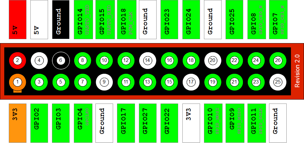
Els números del header són els que he de tenir en compte de cara a les connexions físiques. Els wiringPi pins són els que he de tenir en compte de cara a la programació. Els BCM GPIO no els necessito per a res a no ser que vulgui mirar-me el SoC que munta el Raspberry, que és un xip BCM2835 (Broadcom).
El primer de tot és encendre un led a partir del pin de 3.3V:
i seguidament posar el led connectat al pin del header 11 (wiring pi pin=0), que per defecte està a nivell baix. Ara hauré de començar a programar per tal d'encendre'l. Abans que res m'he d'instal.lar la llibreria wiringPi:
If you haven’t already done so, download and install wiringPi.
This will give you some libraries to use in C programs,
but also a command-line program which we can use to test the GPIO with.
$ sudo apt-get install git-core
$ git clone git://git.drogon.net/wiringPi
$ cd wiringPi
$ ./build
que de fet aquest script el que fa és un make i sudo make install
Un cop instal.lada la llibreria ja puc programar els pins GPIO en mode línia de comanda. Per encendre i apagar el led he de definir el pin 0 com a pin de sortida:
$ gpio mode 0 out
$ gpio write 0 1
$ gpio write 0 0
També es pot utilitzar el GPIO pin numbering:
$ gpio -g mode 17 out
$ gpio -g write 17 1
$ gpio -g write 17 0
Per veure la correspondència entre el wiringPI pin=0 i el BCM GPIO=17 veure https://projects.drogon.net/raspberry-pi/wiringpi/pins/
Si vull fer varis led's com en l'exemple, és similar. Ara vull ficar un interruptor com a input. El puc connectar al wiringPi pin 8, (GPIO-0/SDA0), per una banda, i a terra per l'altra banda. Puc llegir el botó de la següent manera:
gpio mode 8 in
gpio read 8
Quan no apreto l'interruptor la sortida serà 1 (internament el pin té una resistència de 1.8KΩ connectada a 3.3V). Quan apreto l'interruptor la sortida serà 0.
NOTA. Compte! amb els pins. Faig servir el pin 8 perquè té una resistència de pull-up i això la fa especialment vàlida per a fer botons. Puc utilitzar el pin 1 (header 12) com a input?. Sí, doncs és un pin que es pot programar com a I/O, però si el vull habilitar com a input he d'habilitar el pull-up resistor. Llegir https://projects.drogon.net/raspberry-pi/wiringpi/special-pin-functions/
Pins 0 through 7 (GPIO 17, 18, 21, 22, 23, 24, 25, 4 respectively): These are safe to use at any time and can be set to input or output with or without the internal pull-up or pull-down resistors enabled.
També és important tenir present la revisió de la placa, doncs hi ha diferències quant als pins:
$ gpio -v
gpio version: 1.5
Copyright (c) 2012 Gordon Henderson
This is free software with ABSOLUTELY NO WARRANTY.
For details type: gpio -warranty

This Raspberry Pi is a revision 1 board.
I faig el primer programet. Versió bash, prova1_gpio.sh:
#!/bin/bash

#led
red=0
#botó
button=8

# setup:
setup ()
{
  echo Setup
  gpio mode $red out
  gpio mode $button in
}

# waitButton:

waitButton ()
{
  echo -n "Waiting for button ... "
  while [ `gpio read $button` = 1 ]; do
    sleep 0.1
  done
  echo "Got it"
}

# stopTraffic:
#	Cycle the traffic lights from Green to Red
#######################################################################

blinking ()
{
  echo -n "Blinking ... "
  gpio write $red  1
  sleep 0.5
  gpio write $red 0
  sleep 0.5
  gpio write $red  1
  sleep 0.5
  gpio write $red 0
  sleep 0.5
  gpio write $red  1
  sleep 0.5
  gpio write $red 0
  sleep 0.5
  echo "Stopped"
}

# The main program

setup
while true; do
  waitButton
  blinking
done
Versió C, prova1_gpio.c:
#include <stdio.h>
#include <stdlib.h>
#include <unistd.h>
#include <wiringPi.h>

#define	RED		0
#define	BUTTON		8


void setup (void)
{

  if (geteuid () != 0)
  {
    fprintf (stderr, "prova1_gpio: Need to be root to run (sudo?)\n") ;
    exit (0) ;
  }

  if (wiringPiSetup () == -1)
    exit (1) ;

  printf ("Setup ... ") ; fflush (stdout) ;
  pinMode (0, OUTPUT) ;
  digitalWrite (0, 0) ;

  pinMode (BUTTON, INPUT) ;

  printf ("OK\n") ;
}


void waitButton (void)
{
  printf ("Waiting for button ... ") ; fflush (stdout) ;
  while (digitalRead (BUTTON) == HIGH)
    delay (100) ;
  printf ("Got it\n") ;
}


void blinking ()
{
  printf ("blinking ... ") ; fflush (stdout) ;
  digitalWrite (RED,  1) ;
  delay (500) ;
  digitalWrite (RED,  0) ;
  delay (500) ;
  digitalWrite (RED,  1) ;
  delay (500) ;
  digitalWrite (RED,  0) ;
  delay (500) ;
  digitalWrite (RED,  1) ;
  delay (500) ;
  digitalWrite (RED,  0) ;
  delay (500) ;
  printf ("Stopped\n") ;
}

int main (void)
{
  setup () ;
  for (;;)
  {
    waitButton   () ;
    blinking () ;
  }
}
Per compilar i executar la versió de C:
$ cc -o prova1_gpio -Wall -I/usr/local/include -L/usr/local/lib prova1_gpio.c -lwiringPi
$ sudo ./prova1_gpio
En el cas de programar-ho amb C és necessari executar-ho com a sudo perquè si no:
$ ./prova1_gpio
wiringPiSetup: Unable to open /dev/mem: Permission denied
RaspiCAM (mòdul de càmera)
- www.raspberrypi.org/documentation/usage/camera/
Existeix la versió de càmera normal i la de càmera infrarrojos. Jo tinc la de infrarrojos perquè una de les aplicacions possibles és caçar animals a la nit. Però una altra de les aplicacions és el reconiexement d'imatges aplicat a un joc de dardes, tal com es comenta en una altra secció.
Warning: Cameras are static sensitive. Earth yourself prior to handling the PCB. A sink tap or similar should suffice if you don’t have an earthing strap
Característiques:
- http://www.raspberrypi.org/documentation/hardware/camera.md
- http://www.raspberrypi.org/documentation/configuration/camera.md
Still resolution 	5 Megapixels
Video modes 	1080p30, 720p60 and 640x480p60/90
$ sudo raspi-config
Habilitar la càmera
Existeix una llibreria per a Bash i una altra per a Python. En principi interessa la llibreria per bash (des d'un programa C es poden executar comandes de consola).
Les comandes bàsiques per capturar imatges o video són:
$ raspistill: Capturing still photographs with the camera module
$ raspivid: Capturing video with the camera module
$ Time-lapse: Taking pictures at regular intervals and stitching them together in to a video
$ raspiyuv; Capturing still photographs and generating raw unprocessed image files
La primera prova per comprovar que funciona:
$ raspistill -v -o test.jpg
Per fer un video de 10 segons:
$ raspivid -o video.avi -t 10000
<pre>
Full documentation:
*http://www.raspberrypi.org/documentation/raspbian/applications/camera.md

De totes les comandes possibles, de cara al reconeixement d'imatges a mi em pot interessar (comanda raspistillyuv):
<pre>
Extra Options :
--rgb,        -rgb    Save uncompressed data as RGB888
This option forces the image to be saved as RGB data with 8 bits per channel, rather than YUV420.

Note that the image buffers saved in raspistillyuv are padded to a horizontal size divisible by 16 (so there may be unused bytes at the end of each line to make the width divisible by 16). Buffers are also padded vertically to be divisible by 16, and in the YUV mode, each plane of Y,U,V is padded in this way.
amb la qual cosa podem distingir clarament els colors.
Per fer streaming a un altre ordinador està explicat en aquest enllaç:
raspivid -t 999999 -o – | nc [insert the IP address of the client] 5001
PiTFT
NOTA: He de tenir en compte si tinc una touchscreen resistiva o capacitiva. Jo tinc la resistiva. En principi, la diferència entre tots dos eś l'argument del script. Si m'interessés la part de touchscreen, la resistiva s'ha de calibrar.
wget http://adafru.it/pitftsh
mv pitftsh pitft.sh
sudo chmod a+x pitft.sh

sudo ./pitft.sh -t 28r -r #touchscreen resistiu
sudo ./pitft.sh -t 28c -r #touchscreen capacitiu

sudo reboot
Després vénen les següents comandes (que de fet el script ja les fa):
sudo modprobe spi-bcm2708
sudo modprobe fbtft_device name=adafruitts rotate=90
export FRAMEBUFFER=/dev/fb1
startx
Per fer que aquests mòduls es carreguin amb el sistema:
sudo joe /etc/modules
afegir les línies:
spi-bcm2708
fbtft_device

sudo joe /etc/modprobe.d/adafruit.conf
options fbtft_device name=adafruitrt28 rotate=90 frequency=32000000

sudo reboot
dmesg
Si assumim que sempre utiltizarem el framebuffer de la PiTFT:
sudo joe ~/.profile
export FRAMEBUFFER=/dev/fb1
NOTA: la prova que vaig fer amb el model B funcionava. Amb el model B+ hauria de funcionar també sense problemes.
Segueixo el document i funciona a la primera quant a fer veure el video i mostrar la foto. Ara bé, vull fer córrer una aplicació meva SDL, i m'ha donat molts problemes. De fet és impossible, doncs el mòdul PiTFT no implementa l'acceleració gràfica de les targetes de video, i OpenGL i SDL utilitzen aquesta propietat. Per sort, hi ha una manera de poder-ho fer amb Framebuffer mirroring. Està explicat a Sensor_de_temperatura_i_diagrama_de_barres_amb_PiTFT
Configuració wifi USB
- http://www.suntimebox.com/raspberry-pi-tutorial-course/week-3/day2-1-wireless-network-setup/
- http://elinux.org/RPi_USB_Wi-Fi_Adapters
- https://decryption.wordpress.com/2014/05/24/a-very-simple-way-to-use-a-raspberry-pi-as-a-wireless-access-point-not-a-router-with-an-rtl8192cu-based-wi-fi-chipset/
Tinc un TP-LINK TL-WN821N (comprat a PCComponentes, gener 2015)
Segons la pàgina web ha de funcionar. Tinc la versió 4:
- TL-WN821N v3 (ath9k_htc, htc_7010.fw); works out of the box on ArchLinuxARM, Wheezy and on OpenElec (>r11211), Problems with prior OpenElec; needs powered USB Hub (B). This chipset is also compatible with hostapd (wireless AP software)
- TL-WN821N v4 (RLT8192CU), works out of the box on Arch, complains but works. Needs powered USB hub.
Amb un powered HUB el reconeix, si no, no:
$ lsusb
...
Bus 001 Device 041: ID 0bda:8178 Realtek Semiconductor Corp. RTL8192CU 802.11n WLAN Adapter
Per tant queda clar que el meu xip és un RTL8192CU i per tant és la versió 4.
A més:
$ lsmod
Module                  Size  Used by
8192cu                550797  0
$ sudo joe /etc/wpa_supplicant/wpa_supplicant.conf
ctrl_interface=DIR=/var/run/wpa_supplicant GROUP=netdev
update_config=1

network={
ssid="MOVISTAR_1D28"
psk="7FdtpefePfpHJFAXFykd"

# Protocol type can be: RSN (for WP2) and WPA (for WPA1)
proto=WPA

# Key management type can be: WPA-PSK or WPA-EAP (Pre-Shared or Enterprise)
key_mgmt=WPA-PSK

# Pairwise can be CCMP or TKIP (for WPA2 or WPA1)
pairwise=TKIP

#Authorization option should be OPEN for both WPA1/WPA2 (in less commonly used are SHARED and LEAP)
auth_alg=OPEN
}
$ sudo joe /etc/network/interfaces

auto lo

iface lo inet loopback
iface eth0 inet dhcp

allow-hotplug wlan0
iface wlan0 inet dhcp
wpa-conf /etc/wpa_supplicant/wpa_supplicant.conf
La única cosa que he canviat respecte el fitxer original de la distribució Raspbian és iface wlan0 inet manual per iface wlan0 inet dhcp i wpa-roam /etc... per wpa-conf /etc....
$ sudo /etc/init.d/networking restart (Atenció! Perdem la connexió SSH si és així com estem connectats a la RPi)
ifconfig
...
wlan0     Link encap:Ethernet  HWaddr e8:de:27:a2:4d:c4
          inet addr:192.168.1.36  Bcast:192.168.1.255  Mask:255.255.255.0
          UP BROADCAST RUNNING MULTICAST  MTU:1500  Metric:1
miro quina ip té. faig reboot, desconnecto el cable de xarxa, i la propera sessió SSH ja la faig per wireless.
$ sudo reboot
Configuració wifi USB per a casa i local
/etc/wpa_supplicant/wpa_supplicant.conf:
ctrl_interface=DIR=/var/run/wpa_supplicant GROUP=netdev
update_config=1

network={
ssid="MOVISTAR_1D28"
psk="7FdtpefePfpHJFAXFykd"

# Protocol type can be: RSN (for WP2) and WPA (for WPA1)
proto=WPA

# Key management type can be: WPA-PSK or WPA-EAP (Pre-Shared or Enterprise)
key_mgmt=WPA-PSK

# Pairwise can be CCMP or TKIP (for WPA2 or WPA1)
pairwise=TKIP

#Authorization option should be OPEN for both WPA1/WPA2 (in less commonly used are SHARED and LEAP)
auth_alg=OPEN

id_str="casa"
}

network={
ssid="JAZZTEL_5he5"
psk="y9d49pvj9hbf"

proto=RSN
key_mgmt=WPA-PSK
pairwise=CCMP
auth_alg=OPEN
id_str="local"
}
NOTA. En el local la seguretat és WPA2-PSK. Per tal de què funcioni he de ficar:
- proto=RSN
- key_mgmt=WPA-PSK
- pairwise=CCMP
doncs:
- https://www.raspberrypi.org/forums/viewtopic.php?t=50312&p=416523
- If you router encryption is set to AES then set the encryption on the RPi to CCMP.
- Protocol type can be: RSN (for WP2) and WPA (for WPA1)
Ara també funciona en el local.
/etc/network/interfaces:
auto lo

iface lo inet loopback
iface eth0 inet dhcp

allow-hotplug wlan0
iface wlan0 inet dhcp
wpa-conf /etc/wpa_supplicant/wpa_supplicant.conf
iface casa inet dhcp
iface local inet dhcp
En el cas de què vulgui una IP fixa, el fitxer /etc/network/interfaces queda de la següent manera:
auto lo
iface lo inet loopback

iface eth0 inet dhcp

allow-hotplug wlan0
iface wlan0 inet manual
wpa-roam /etc/wpa_supplicant/wpa_supplicant.conf
iface casa inet static
address 192.168.1.50
netmask 255.255.255.0
gateway 192.168.1.1

iface default inet dhcp
NOTA. És important veure que (a diferència del que hi ha més amunt) he ficat wpa-roam en comptes de wpa-conf. La última línia iface default inet dhcp no és necessària.
Raspberry Pi 3 (wifi integrada) Configuració wifi USB per a casa i local
Em connecto per SSH amb el cable de xarxa, i escanejo les xarxes wifi
$ sudo iwlist wlan0 scan
- ESSID casa: MOVISTAR_1D28
- ESSID local: JAZZTEL_5he5
$ sudo joe /etc/wpa_supplicant/wpa_supplicant.conf
Igual que he fet abans:
ctrl_interface=DIR=/var/run/wpa_supplicant GROUP=netdev
update_config=1

network={
ssid="MOVISTAR_1D28"
psk="7FdtpefePfpHJFAXFykd"

# Protocol type can be: RSN (for WP2) and WPA (for WPA1)
proto=WPA

# Key management type can be: WPA-PSK or WPA-EAP (Pre-Shared or Enterprise)
key_mgmt=WPA-PSK

# Pairwise can be CCMP or TKIP (for WPA2 or WPA1)
pairwise=TKIP

#Authorization option should be OPEN for both WPA1/WPA2 (in less commonly used are SHARED and LEAP)
auth_alg=OPEN

id_str="casa"
}

network={
ssid="JAZZTEL_5he5"
psk="y9d49pvj9hbf"

proto=RSN
key_mgmt=WPA-PSK
pairwise=CCMP
auth_alg=OPEN
id_str="local"
}
$ sudo ifdown wlan0
$ sudo ifup wlan0

$ ifconfig

wlan0     Link encap:Ethernet  HWaddr b8:27:eb:a8:e6:00
          inet addr:192.168.1.40  Bcast:192.168.1.255  Mask:255.255.255.0
          inet6 addr: fe80::4c4a:3733:f4b9:3f73/64 Scope:Link
          UP BROADCAST RUNNING MULTICAST  MTU:1500  Metric:1
          RX packets:108 errors:0 dropped:89 overruns:0 frame:0
          TX packets:30 errors:0 dropped:0 overruns:0 carrier:0
          collisions:0 txqueuelen:1000
          RX bytes:33864 (33.0 KiB)  TX bytes:5812 (5.6 KiB)
Muntar una memòria USB Flash (pen drive)
Formato el llapis USB Flash Kingston de 4GB, amb format FAT.
$ ls -l /dev/disk/by-uuid/
total 0
lrwxrwxrwx 1 root root  9 Apr 10 08:01 27D6-A4AA -> ../../sda
lrwxrwxrwx 1 root root 15 Jan  1  1970 3d81d9e2-7d1b-4015-8c2c-29ec0875f762 -> ../../mmcblk0p2
lrwxrwxrwx 1 root root 15 Mar 31 16:17 787C-2FD4 -> ../../mmcblk0p1
The line will usually refer to /sda and in this example it is sda1. My ID is 18A9-9943. Note down yours.
Creem un punt de muntatge:
$ sudo mkdir /media/usb
$ sudo chown -R pi:pi /media/usb
Muntem manualment el llapis:
$ sudo mount /dev/sda /media/usb -o uid=pi,gid=pi,iocharset=utf8
i ja funciona:
$ ls -la /media/usb/
total 28
drwxr-xr-x  7 pi   pi   4096 Jan  1  1970 .
drwxr-xr-x  3 root root 4096 Apr 10 08:05 ..
drwxr-xr-x 21 pi   pi   4096 Apr  9 16:34 Entrega_Examen_AJAX
drwxr-xr-x  4 pi   pi   4096 Apr 10  2015 musica_rockola
drwxr-xr-x  3 pi   pi   4096 Apr  9 11:04 omplir_bd
drwxr-xr-x  3 pi   pi   4096 Apr  9 22:50 rockola_frontend
Ens interessa fer automount en l'inici del sistema:
$ sudo joe /etc/fstab
Al final de tot afegim:
UUID=27D6-A4AA /media/usb auto,users,rw,uid=pi,gid=pi,iocharset=utf8 0 0
o millor en el meu cas:
UUID=27D6-A4AA /media/usb vfat auto,users,rw,uid=pi,gid=pi,iocharset=utf8 0 0
NOTA: de la primera manera no em funciona, i amb la segona manera forço que detecti el filesystem a FAT32.
NOTA: Per tal de què els fitxers que contenen accents i caràcters especials, és important muntar el filsystem amb codificació UTF8: opció -o iocharset=utf8
i reiniciem:
$ sudo reboot
Per desmuntar:
$ umount /media/usb
$ sudo umount /media/usb (si hem utiltizat fstab)
NOTA: hem deixat que la comnda mount determini automàticament el filesystem. Si vull especificar que tinc fomrat FAT32:
$ sudo mount /dev/sda /media/usb -o uid=pi,gid=pi,iocharset=utf8 -t vfat
Fer una ISO d'una targeta SD
PiPlay_(abans_PiMAME)#Fer_un_backup_de_la_targeta_SD
USB Audio Card
El so va millorar molt de la RPi B a la RPi B+ (amb la sortida analògica, jack). Sembla que pot millorar més si utilitzem un USB Audio Card. És a dir, s'ha de configurar la RPi per tal de què el so surti per USB, i aquest aparell converteix el so digital a analògic, sense soroll. S'ha de provar en les meves màquines, doncs la qualitat del so és un tema pendent.
- http://piplay.org/forum/discussion/2112/mini-cocktail-arcade
- http://computers.tutsplus.com/articles/using-a-usb-audio-device-with-a-raspberry-pi--mac-55876
$ lsusb
...
Bus 001 Device 004: ID 0d8c:013c C-Media Electronics, Inc. CM108 Audio Controller
$ amixer
Simple mixer control 'PCM',0
  Capabilities: pvolume pvolume-joined pswitch pswitch-joined penum
  Playback channels: Mono
  Limits: Playback -10239 - 400
  Mono: Playback 400 [100%] [4.00dB] [on]
Per tal de fer què la USB Audio Card sigui per defecte, comento (comentant faig que no passi a ser la última):
$ sudo joe /etc/modprobe.d/alsa-base.conf
#options snd-usb-audio index=-2
I reinicio, i ara ja tinc que la USB Audio Card està per defecte:
$ sudo reboot

$ amixer
Simple mixer control 'Speaker',0
  Capabilities: pvolume pswitch pswitch-joined penum
  Playback channels: Front Left - Front Right
  Limits: Playback 0 - 151
  Mono:
  Front Left: Playback 44 [29%] [-20.13dB] [on]
  Front Right: Playback 44 [29%] [-20.13dB] [on]
Simple mixer control 'Mic',0
  Capabilities: pvolume pvolume-joined cvolume cvolume-joined pswitch pswitch-joined cswitch cswitch-joined penum
  Playback channels: Mono
  Capture channels: Mono
  Limits: Playback 0 - 127 Capture 0 - 16
  Mono: Playback 2 [2%] [0.37dB] [off] Capture 0 [0%] [0.00dB] [on]
Simple mixer control 'Auto Gain Control',0
  Capabilities: pswitch pswitch-joined penum
  Playback channels: Mono
  Mono: Playback [on]
A més:
$ amixer cset numid=3 1
numid=3,iface=MIXER,name='Mic Playback Volume'
  ; type=INTEGER,access=rw---R--,values=1,min=0,max=127,step=0
  : values=1
  | dBminmax-min=0.00dB,max=23.81dB
(ho puc ficar en línia de comanda, o sinó està definit a /home/pi/.bashrc)
Funciona correctament, i s'ha de pujar el so amb alsamixer
$ alsamixer

$ aplay /usr/share/scratch/Media/Sounds/Vocals/Singer1.wav
Però quan arrenco el 'mame4all no funciona, i això li ha passat a altra gent:
$ ./mame pacplus
Segmentation faultitialize...set params) Rate doesn't match (requested 44100Hz, get 0Hz)
Li ha passat a més gent:
i la solució:
$ sudo joe /etc/asound.conf
ctl.!default {
type hw
card 0
}
pcm.usb
{
type hw
card "U012529205"
format S16_LE
}

pcm.!default {
type asym
playback.pcm
{
type plug
slave {
pcm "hw:0"
format S16_LE
}
}
capture.pcm
{
type plug
slave.pcm "usb"
}
}
I ara sí que funciona, però sincerament, no veig que hagi millorat el so. Al contrari, prefereixo el so del jack analògic (RPi B+). Sembla ser com es comenta en l'enllaç que la qualitat del so tindria a veure amb la resolució de la pantalla.
LED chaser: I2C i MCP23017 a la RPi
$ sudo joe /etc/modprobe.d/raspi-blacklist.conf
#blacklist i2c-bcm2708

$ sudo joe /etc/modules
i2c-dev

$ sudo apt-get install i2c-tools
$ sudo adduser pi i2c
$ sudo shutdown -r now
$ sudo i2cdetect -y 1
     0  1  2  3  4  5  6  7  8  9  a  b  c  d  e  f
00:          -- -- -- -- -- -- -- -- -- -- -- -- --
10: -- -- -- -- -- -- -- -- -- -- -- -- -- -- -- --
20: 20 -- -- -- -- -- -- -- -- -- -- -- -- -- -- --
30: -- -- -- -- -- -- -- -- -- -- -- -- -- -- -- --
40: -- -- -- -- -- -- -- -- -- -- -- -- -- -- -- --
50: -- -- -- -- -- -- -- -- -- -- -- -- -- -- -- --
60: -- -- -- -- -- -- -- -- -- -- -- -- -- -- -- --
Per tal de què detecti el dispositiu, ha d'estar el MCP23017 connectat. Si surten tot zeros, és el moment de connectar el MCP23017 i fer el LED chaser:
Ara ja vull executar el script python. Primer instal.laré la llibreria per a Python:
$ sudo apt-get install python-smbus
ledchaser.py:
! /usr/bin/python

# A simple Python command line tool to control an MCP23017 I2C IO Expander
# By Nathan Chantrell http://nathan.chantrell.net
# GNU GPL V3

# SK Pang Electronics June 2012

import smbus
import sys
import getopt
import time
bus = smbus.SMBus(0)

address = 0x20 # I2C address of MCP23017
bus.write_byte_data(0x20,0x00,0x00) # Set all of bank A to outputs
bus.write_byte_data(0x20,0x01,0x00) # Set all of bank B to outputs


def set_led(data,bank):
	if bank == 1:
		bus.write_byte_data(address,0x12,data)
	else:
		bus.write_byte_data(address,0x13,data)
	return

# Handle the command line arguments
def main():
	a = 0
	delay = 0.05
	while True:

		# Move led left
		for x in range(0,8):
			a = 1 << x
			set_led(a,0)
			time.sleep(delay)
			set_led(0,0)
		for x in range(0,8):
			a = 1 << x
			set_led(a,1)
			time.sleep(delay)
			set_led(0,1)

		# Move led right
		for x in range(7,-1,-1):
			a = 1 << x
			set_led(a,1)
			time.sleep(delay)
			set_led(0,1)

		for x in range(7,-1,-1):
			a = 1 << x
			set_led(a,0)
			time.sleep(delay)
			set_led(0,0)


if __name__ == "__main__":
	main()
Operador <<:
x << y
    Returns x with the bits shifted to the left by y places (and new bits on the right-hand-side are zeros). This is the same as multiplying x by 2**y.
Per tant, el que fem és:
for x in range(0,8):
   a = 1 << x

x=0
  a=1<<0 -> a=1 -> 00000001

x=1
  a=1<<1 -> a=10 -> 00000010

x=2
  a=1<<2 -> a=100 -> 00000100

x=3
  a=1<<3 -> a=1000 -> 00001000

x=4
  a=1<<4 -> a=10000 -> 00010000

x=5
  a=1<<5 -> a=100000 -> 00100000

x=6
  a=1<<6 -> a=1000000 -> 01000000

x=7
  a=1<<7 -> a=10000000 -> 10000000
El meu dispositiu està en la direcció 0x20, però té dos bancs. Cada banc és un byte. Per tant, puc adreçar dos bytes i 16 bits (que seran 16 leds)
He implementat diferents efectes en el marc del projecte de la rockola. Video:
Fer conectors per la GPIO. Conectors per crimpar i ficar en els housings
Vaig fer dues compres, la primera em va sortir malament, la segona bé.
13/10/15

1839928 -> aquest és el que funciona
AMPHENOL  MF30-HF1T  Contacto, Serie MF30, Hembra, Crimpado, 20 AWG, Contactos Chapados en Estaño
Serie MF30
Para Usar Con: MF3.0 Power Connectors

19/10/16
1840051 -> massa gran per als pins GPIO
AMPHENOL  MF42-HFT  Contacto, Serie MF42, Hembra, Crimpado, 24 AWG, Contactos Chapados en Estaño, Connector Housing
Rango de Producto: Serie MF42
L'error ve de què em vaig fixar en la gauge AWG, i m'havia de fixar en la sèrie MF.
- 20 AWG -> 0.5176mm2 -> això no és el que m'importa per insertar-ho en un pin GPIO
- 24AWG -> 0.2047mm2 -> això no és el que m'importa per insertar-ho en un pin GPIO
- MF30: la punta té una secció de 1,35mm -> aquest és el correcte
- MF42: la punta té una secció de 1,7mm -> i aquest balla en els pins del GPIO
S'ha de mirar els pdfs amb les especificacions tècniques.
Conclusió: he comprat malament perquè m'he fixat en els cables que admet (gauge en AWG). I el que m'he de fixar és en la sèrie MF. Per als pins GPIO de la RPi, el que val és MF30 i no pas MF42.
A Farnell es troben a:
Inicio
> Conectores
> Conectores Macho y Hembra y Componentes
> Contactos para Conectores Macho y Hembra
> MF30-HF1T
nota juny 2018: he comprat cable AWG30. Malament! Aquest cable és molt prim.
Setting up a Raspberry Pi as an access point in a standalone network (NAT)
Es tracta de què la RPi sigui un Access Point, és a dir que doni IPs per DHCP. D'aquesta manera es pot crear una xarxa local independent. Això és útil a l'institut quan volem que tots els alumnes es conectin a una mateixa xarxa local sense passar per els routers i firewalls de l'institut.
A més, si volem que tots aquests dispositius tinguin accés a Internet, s'ha de fer un bridge entre la eth0 (cablejada, que dóna accés a Internet) i la wlan0 (que és la wireless que dóna IP's a tots els dispositius connectats). D'aquesta manera, tots els dispositius connectats tindran accés a Internet.
Ha funcionat bé tots els passos. La única cosa que m'he entretingut és en el fitxer sudo nano /etc/dnsmasq.conf, que ha de ser:
interface=wlan0
dhcp-range=192.168.4.2,192.168.4.20,255.255.255.0,24h
març 2019: he tingut més problemes. He hagut de fer el update i el upgrade de la targeta.
No podia fer:
sudo systemctl start hostapd
sudo systemctl start dnsmasq
perquè diu que el servei està masked. To unmask a service run:
systemctl unmask name.service

per tant:

systemctl unmask hostapd.service
Aquests dos serveis no s'aixequen en l'inici del sistema, així que aquestes dues comandes les fico en el /etc/rc.local.
Per tenir bridge o no només cal commutar aquestes dues línies:
...
bridge=br0
#driver=nl80211
...
Si faig bridge, en el portàtil tindré conneió a Internet, i la IP que veuré serà del tipus 192.168.1.x. Si no faig bridge no tinc connexió a Internet, la IP serà del tipus 192.168.4.x, i puc fer ping a la RPi (192.168.4.1)
Streaming amb RPi3 + Raspicam
(juliol 2020). 2 possibilitats (són equivalents)
configuració raspi-config
$ sudo raspi-config
selecciono que el boot sigui CLI, sense desktop. Ja no em cal.
habilito SSH, la raspicam, el boot CLI sense password), la configuració wifi (MOVISTAR_5084, pwd:282899Y47U323B424g2u), etc.
També és important canviar la memòria de video (GPU) a 256MB (per defecte està a 128MB)
possibiltat 1
$ python3 rpi_camera_surveillance_system.py
En el navegador web:
$ sshpass -p 'Sh******' ssh pi@192.168.1.62
possibiltat 2
Va millor, menys latència.
Primer de tot, instal·lo els drivers de UV4L
- https://www.instructables.com/id/Raspberry-Pi-Video-Streaming/
- http://www.linux-projects.org/uv4l/installation/
$ sudo pkill uv4l

$ sudo uv4l -nopreview --auto-video_nr --driver raspicam --encoding mjpeg --width 640 --height 480 --framerate 10 --server-option '--port=9000' --server-option '--max-queued-connections=30' --server-option '--max-streams=25' --server-option '--max-threads=29'
i amb els paràmetres quem em van millor:
$ sudo uv4l -nopreview --auto-video_nr --driver raspicam --encoding mjpeg --width 800 --height 600 --framerate 20 --server-option '--port=9090' --server-option '--max-queued-connections=30' --server-option '--max-streams=25' --server-option '--max-threads=29' --rotation=180 --sharpness=100 --saturation=-80
En el navegador web:
El delay és molt poc. Però compte! que abans era dolent. I per què? doncs no era per culpa de la RPi, sinó del portàtil. Tenia la RPi amb cable i el portàtil HP amb wireless, i m'anava fatal. Ara que tinc el portàtil amb cable i la RPi amb wifi, em va molt bé.
(ara el script de python també va bé, encara que el delay és més que amb el driver v4l)
més arguments:
--rotation=180 --sharpness=100 --saturation=-80
--saturation -> puc corregir la imatge que es veu vermella (és una càmera IR), i ara ja es veu en b/n
Videoconferència amb meet
Ara que tinc una pestanya del navegador amb la imatge de la raspicam, ara n'hi ha prou en iniciar una conferència, i compartir la pestanya del google chrome. He fet un parell de proves amb connexió remota, i la qualitat del video i del delay són suficients (si bé no és perfecte).
Obrir els ports del router
- 192.168.1.1
- pwd: gewn5gJ8
obrim els ports 9000 -> 9000 (TCP+UDP) (de fet, és UDP)
Per saber la meva IP pública:
wget -qO- http://ipecho.net/plain
83.42.22.15
I ara ja es pot accedir a la webcam directament des del navegador: (però sense so)
creat per Joan Quintana Compte, desembre 2012, novembre 2015, setembre 2016, juliol 2018, juliol 2020